Solutions
Frequently Asked Questions
Select a category, or browse all categories.
General
Installation
Near or under water
Do you have a question we haven’t answered?
Contact Peterson today.
Solutions
Frequently Asked Questions
Remove screws from side of housing. Lift off the lens retainer ring and the lens. Then lift out the inside reflective piece that holds the bulb. Unclip the two wires that hold the bulb in place and pull the bulb out. Next, pull back the rubber piece that covers the blade terminals and pull apart those apart (you will need to use needle nose pliers). Replace the bulb, but do not touch the actual bulb.
The issue is most likely with the chassis ECU. You can add external resistors. LED’s draw very little amps and the module is not recognizing them. The chassis manufacturer may also be able to reprogram the ECU for you.
The unit is not designed to be the primary warning device. It is a traffic flow assistance device to be used in conjunction with other warning signals. It could possibly meet Class 2 but has not been tested as such.
The 169 lamps should be capable of being mounted by two #8 screws.
Yes, these lamps have been changed. The older V133XR had 2 red LEDs and the newer V133XR has 3 red LEDs. This change was made so the same LED PCB and lens tooling could be used for both the Amber and Red lamps. Change was made about 3/2006. The current draw of the lamp was not changed.
LED lamps typically appear brighter to the human eye because the LED lamps emit a narrower range of color light where as the incandescent lamps emit a broader range of color light. The actual light intensity of LED or incandescent lamps (with the same function) is generally about the same.
Recommended in-line fuse for one lamp would be ½ Amp or 1 Amp fuse. A higher current fuse such as a 3 Amp or even a 5 Amp fuse could be used to protect the wiring.
No.
LED lights will not draw enough current to make it work properly. We would recommend that a resistor (6.2 ohm approx. / 50 watt) be placed in line to generate the current draw needed to make the flasher function properly.
The term “Heavy Duty” when referring to flashers typically means being able to operate more lamps and higher currents.
Examples:
554 & 557: 10 lamp (21 Amp) Standard flasher
570 & 571: 12 lamp (25.2 Amp) Standard flasher
573 & 574: 16 lamp (44.6 Amp) Heavy Duty flasher
576 & 577: 20 lamp (45 Amp) Heavy Duty flasher
All of these flashers do generate a sound when they operate because of the sound the internal electromechanical relay makes when the relay contact close. The intensity or decibel (db) sound level of the noise that these flashers make has not specified, quantified or defined.
An all solid state flasher like the PM 5000 flasher operates without generating any sound or noise.
I have seen some flasher data sheets from companies like Hella that do list a sound level specification for some of their flashers. The PM flashers are not rated with this type of specification.
Ion coating is a process to harden the glass and make it more resistant to breaking from road debris. Some of our other products also have hardened glass, but it is done by a different process. It’s hard to say if one process is better than the other. It really comes down to cosmetics. The Ion coating gives the lens the blue cast and the other processes do not.
The following solvents/cleaners ARE COMPATIBLE with polycarbonate:
Mild soap and water
Mineral Spirits
Hexane
VM & P Naphtha
Varsol No. 2
#1 & #3 denatured alcohol
Freone TF & TE-35
Ethanol
10% Sol Bon Ami®
Dirtex®
2% Sol. Reg. Joy
Heptane
White Kerosene
Methyl, isopropyl & isobutyl alcohols
Lacryl® PCL-2035
polycarbonate cleaner
Petroleum Ether/65 degrees C boiling point
The following solvents/cleaners MUST NOT be used with polycarbonate:
Trichlor
Acetone
Triclene®
Methyl Ethyl Keytone (MEK)
MIBK
Toluol
Benzol
Gasoline
Carbon Tetrachloride
Chlorinated Hydrocarbons
Texize-8006, 8129, 8758
Liquid Cleaner – 8211
Agitene®
Ajax®
All Liquid Detergents
Pink Lux® (phosphate free)
Diversol®
Lemon Joy® (phosphate free)
Kleenol Plastics
Lestoil®
Lysol®
Stanisol Naphtha®
Oils
Engineering pulled a unit from stock – it takes approx.. 2 lbs of force to exceed the detent and actuate the turn signal lever.
The indicator light bulb (1816 12V 3W) draws 0.322 Amps. The customer may want to know what the maximum current capability is for this switch instead of the current draw. If this is what the customer wants to know, our print calls out that this switch is to meet the SAE J589. Per the SAE J589 the maximum current rating for this switch is 5 Amps.
No, the 500 switch does not have automatic cancelling feature.
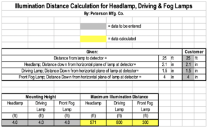
The pattern provided is a “driving” pattern, this is essentially an auxiliary high beam lamp.
1) After removing trailer from launching ramp, wash down the inside and outside of your trailer lights to prevent corrosion of the socket.
2) Silicone spray the mounting areas around the bulb to prevent corrosion.
3) Buy trailer lights with extended life bulbs. Most Peterson lights come with 15,000 hour bulbs, which can be identified by their distinctive green base.
When your car lighting system has a separate turn-signal lamp from the brake and tail light. The V5410 is an electronic trunk connector which converts vehicle lighting systems with separate turn signals to the conventional trailer lighting system.
Before purchasing replacement lights, clean the mounting bolts on the existing lights with a wire brush. Many lights ground through the mounting hardware and an improper or “bad” ground is the primary cause for lights not working.
Cut the trailer plug from the old harness and tie the end of the new harness to the old. Then carefully pull the old harness out the rear of the trailer.
Car-side plug has its pins protected or shrouded.
The directions are clear. Peterson follows standard wiring guidelines. Brown is tail, green and yellow are turn, etc.
Was not grounded properly to the steering column.
To check the right turn function: Connect the green wire to positive (+) and the red wire to ground and the right turn output function of the 5410 converter should operate. To check the left turn function: Connect the yellow wire to positive (+) and the red wire to ground and the left turn output function of the 5410 converter should operate. To check the Stop function: Connect the red wire to positive (+) and either or both the green and/or yellow wire to ground and the stop output function of the 5410 converter should operate. The Brown wire (Tail) and white wire (ground) are straight through wires.
Following is chart which can be modified to show this distance.
It is a positive ground so you hook the power up to the black wire then place the other wires on the ground depending on what color you desire. For example, if you want a red light you put the power on the black wire and then put the red wire to the ground. If you want a purple light, then you would put the black to the power and the red and blue wires to the ground.
Submersible lights use the bell-jar concept. This allows a small amount of water inside the housing. The resulting air pressure inside the cavity prevents any additional water from reaching the area where the contacts and sockets are located. Waterproof is usually associated with a completely sealed light. Competitors often claim their light is waterproof, but in actuality, their light also uses the bell-jar concept.
You would measure across the widest width of the trailer. If the measurement is 80” or above, you must purchase a light kit that is approved for over 80” trailers. If the trailer measures less than 80”, you can use any other light kit which is available.
Be sure to unplug wire harness and let lights cool down. Use lithium grease in the socket to reduce the corrosion that water can cause.
No.
Do you have a question we haven’t answered?
Contact Peterson today.